 GLORY MACHINERY | Metal Polishing & Grinding Solutions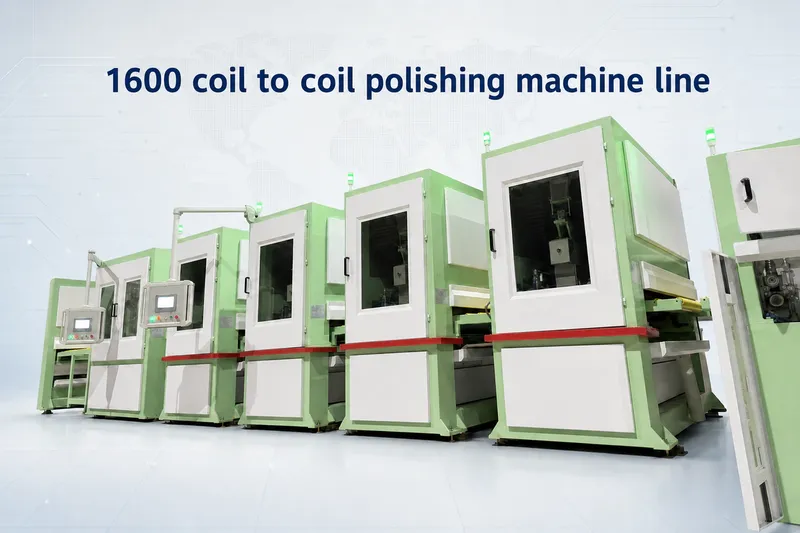
Stainless Steel Coil Polishing Line
Product Overview
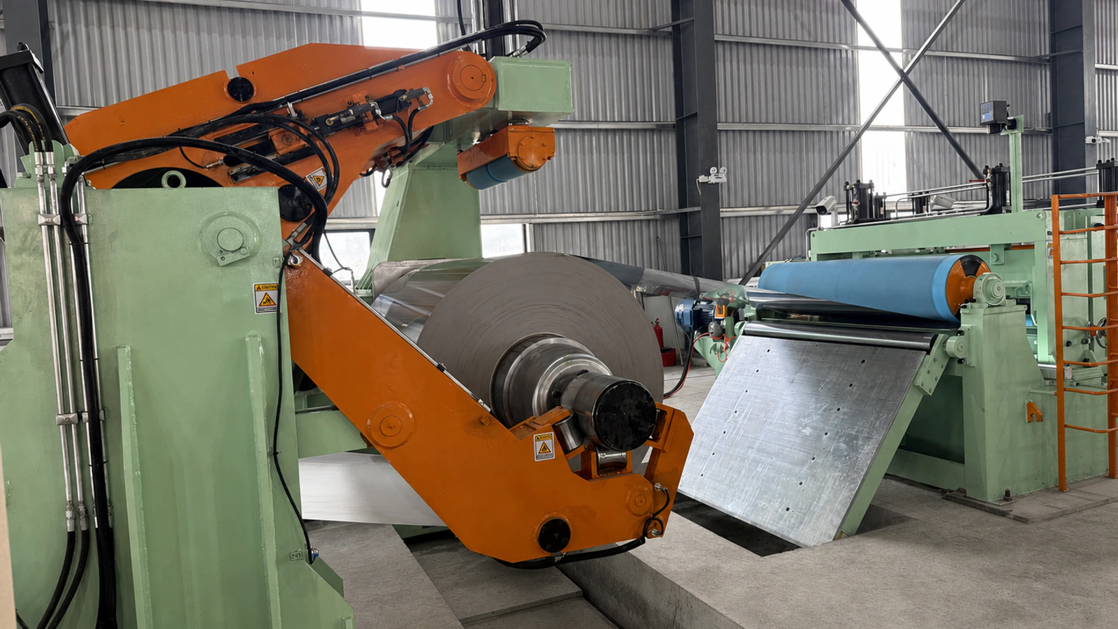
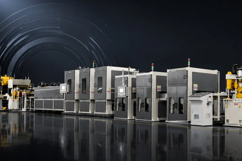
The MJD1600 is an oil-wet coil-to-coil polishing and grinding line for continuous steel-coil surface processing. The documented process integrates coil loading, powered decoiling, strip feeding and leveling, crop shearing, No.4 abrasive-belt polishing, four-head hairline finishing, cleaning and drying, protective-film application, post-tensioning, EPC-guided recoiling, and auxiliary coil handling.
The source document specifies a material thickness range of 0.3-3.0 mm. It contains different width limits for the complete line and individual machines; the approved working width must therefore be confirmed for each project.
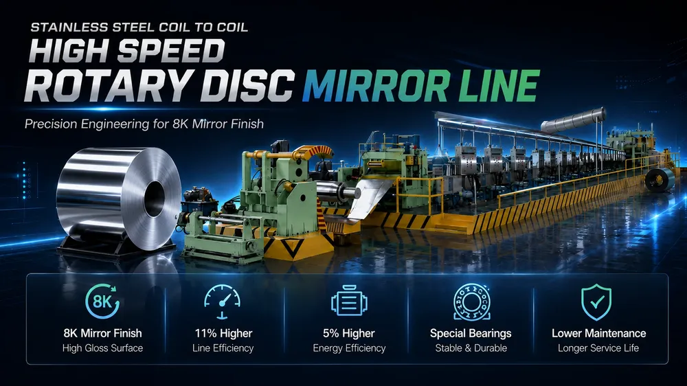
For 8K mirror requirements, see our coil-to-coil 8K mirror polishing line.
>Key Features
- stainless steel coil polishing machine
- coil polishing machine
- no.4 finishing line
Machine Advantages
Integrated Production Flow
The line connects coil handling, strip preparation, surface finishing, cleaning, film protection, and recoiling in one production sequence. This reduces intermediate coil transfers between the documented process stages.
Dual-Side No.4 Configuration
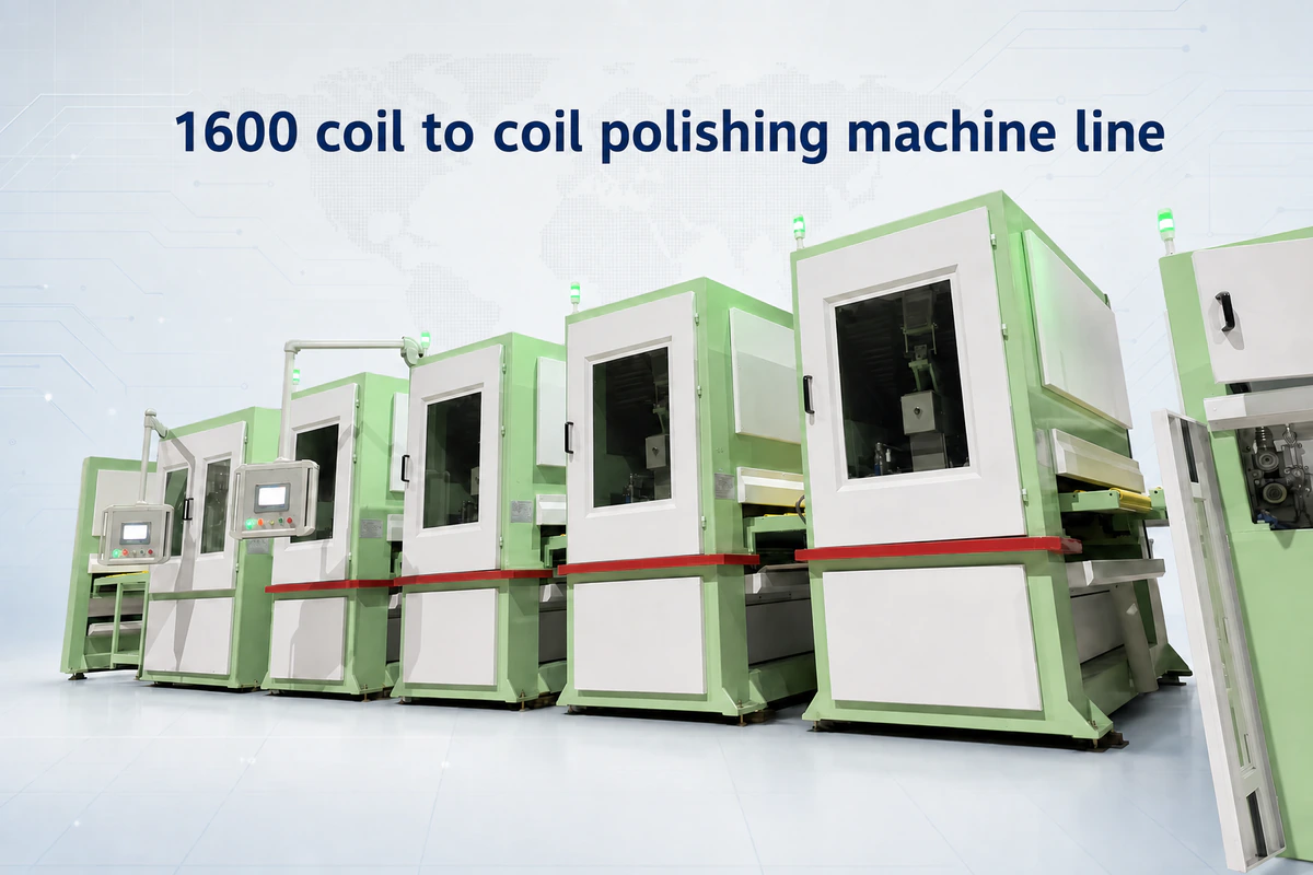
The documented configuration uses three No.4 polishing units for the back side and five units for the top side, for a total of eight polishing units.
Combined No.4 and Hairline Capability
No.4 abrasive-belt polishing and four-head hairline processing are included in the same documented line configuration.
Controlled Coil Handling
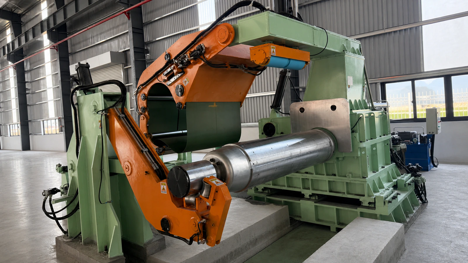
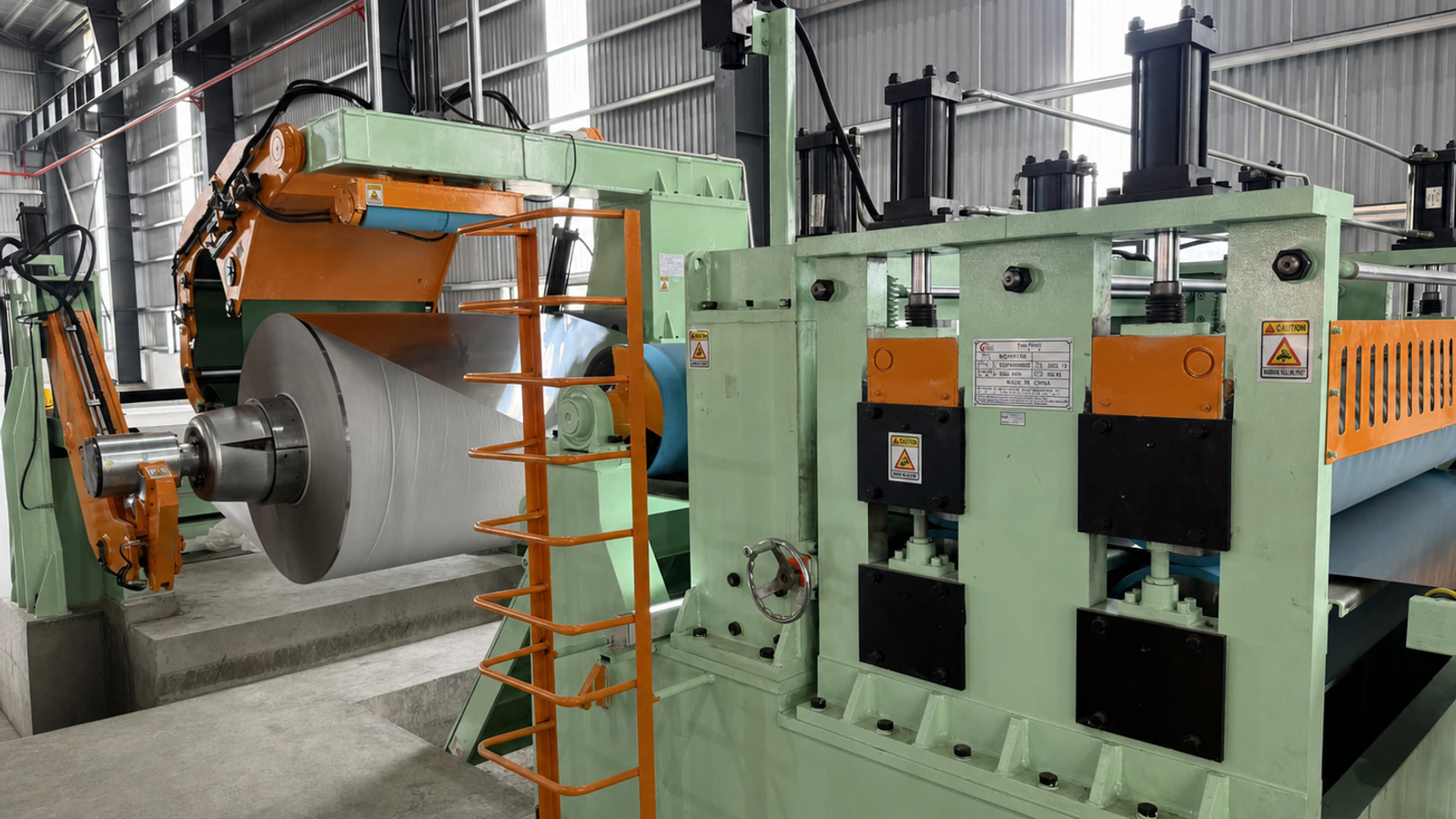
Hydraulic loading and unloading trolleys, support arms, powered mandrels, pinch rolls, and auxiliary feeding devices support coil transfer through the line.
Recoiling Alignment Control
The recoiler includes an EPC system consisting of a detection lens, light source, control module, servo valve, and feedback sensor for winding-position correction.
Surface Protection After Finishing
The line includes brush cleaning, high-pressure air drying, and double-sided protective-film application after polishing.
Main Machine Components
The 1600 coil-to-coil polishing line combines coil handling, strip preparation, No.4 polishing, hairline finishing, cleaning, film application, and EPC-guided recoiling in one integrated production system. The principal components documented in the technical quotation are listed below.
| No. | Component | Function / Configuration | Quantity |
|---|---|---|---|
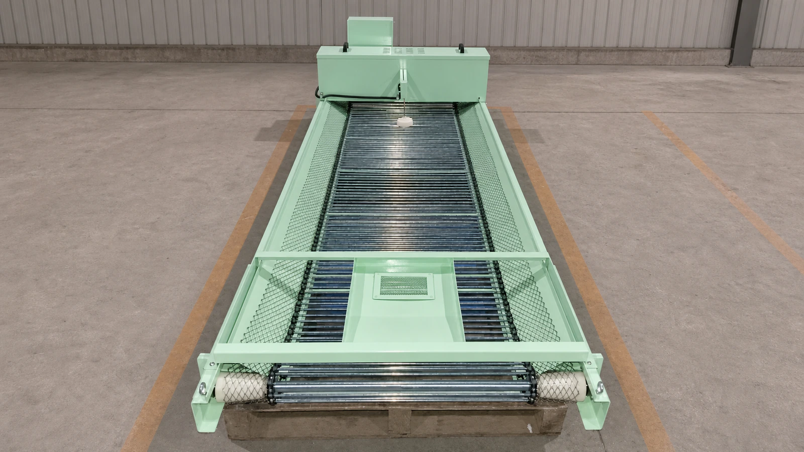
| 1 | Material preparation table | Welded steel structure for holding incoming coils; surface lined with nylon sheet | 1 set |
| 2 | Loading unit with telescopic guard plate | Guide-column loading trolley with hydraulic lifting and a moving pit cover | 1 set |
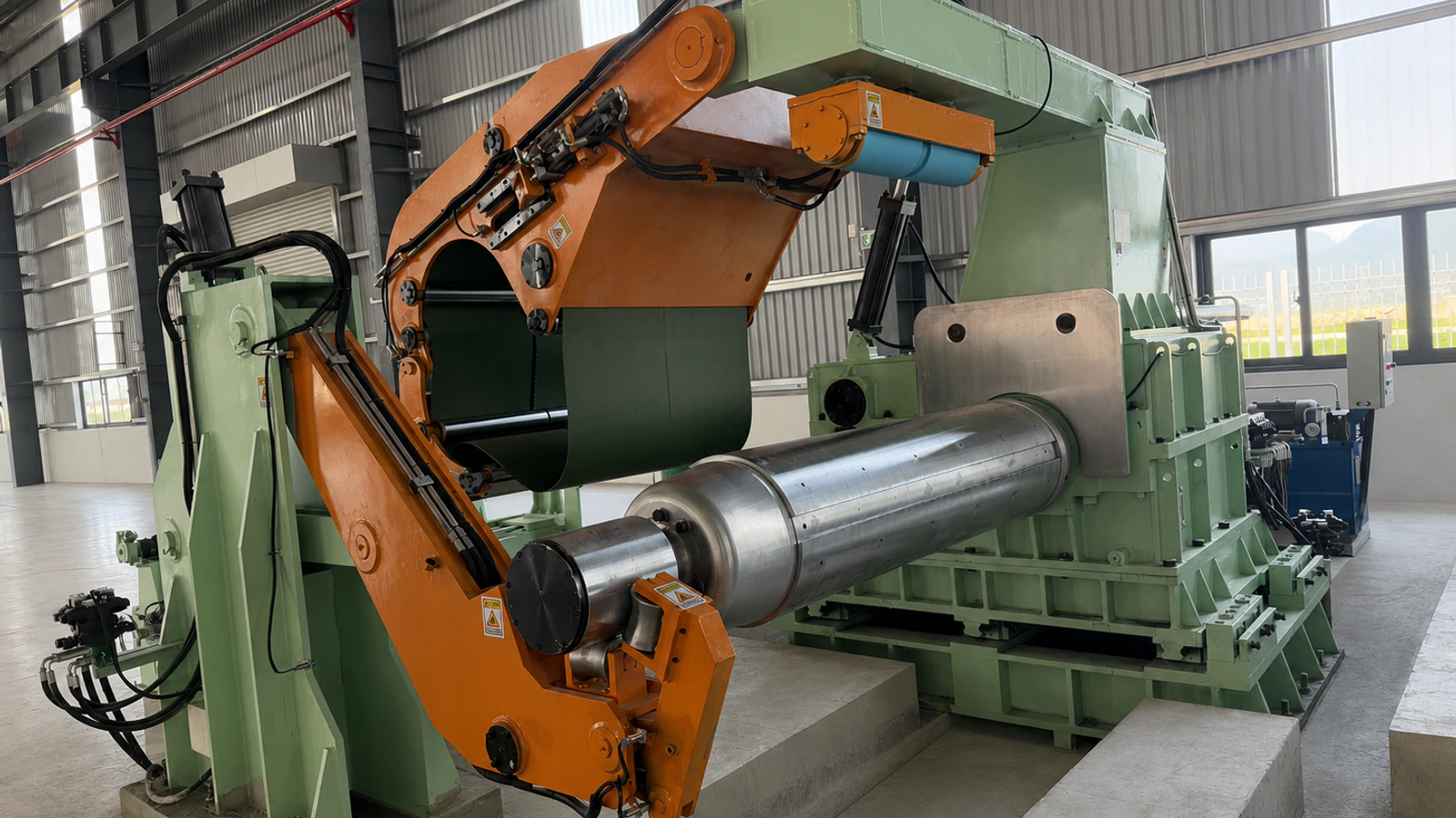
| 3 | Front support arm | Hydraulically operated support for the cantilever end of the decoiler mandrel | 1 set |
| 4 | Paper recoiler | Tension-type paper collection system with paper-break detection and alarm | 1 set |
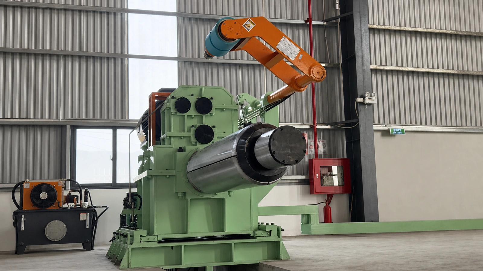
| 5 | Hydraulic decoiler | Powered, counter-tension decoiler with hydraulic mandrel expansion and pressure arm | 1 set |
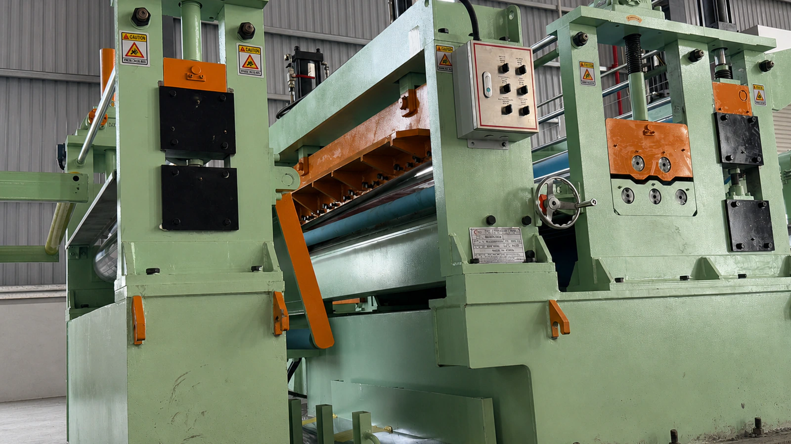
| 6 | Pinch roll, five-roll leveling, side guiding, and crop shear | Strip feeding, leveling, lateral guidance, and hydraulic head/tail cropping | 1 set |
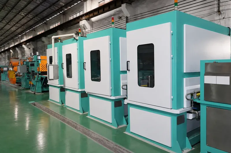
| 7 | 1650 No.4 polishing machine | Three units for the back side and five units for the top side | 8 sets |
| 8 | Four-head hairline machine | Abrasive hairline finishing with four grinding heads | 1 set |
| 9 | Cleaning and drying system | Brush cleaning, water circulation, high-pressure blowers, and air-knife drying | 1 set |
| 10 | Film applicator | Double-sided film application with air shafts and magnetic-powder brakes | 1 set |
| 11 | Four-roller pinch roll and guide roller | Post-finishing strip conveyance, clamping, guidance, and tension assistance | 1 set |
| 12 | Rear support arm | Hydraulically operated support for the cantilever end of the recoiler mandrel | 1 set |
| 13 | Paper feeder | Constant-tension lining-paper unwinding with paper-break detection | 1 set |
| 14 | Unloading trolley | Guide-column trolley for finished-coil unloading with telescopic pit cover | 1 set |
| 15 | Recoiler with EPC system and auxiliary recoiling device | Hydraulic mandrel, pressure arm, EPC correction, and auxiliary feeding/recoiling | 1 set |
| 16 | Filtration system | Nonwoven-fabric centralized filtration for water-soluble grinding fluid | 1 set |
| 17 | Hydraulic system | Hydraulic station, valve blocks, piping, and cylinders for handling and alignment | 1 set |
| 18 | Pneumatic system | Air-treatment components, solenoid valves, pipelines, and cylinders | 1 set |
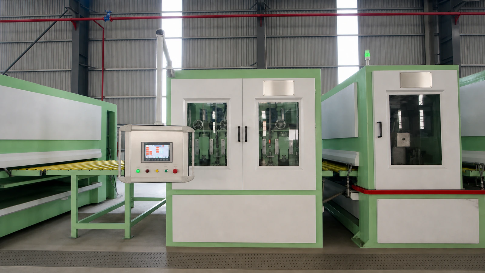
| 19 | Electrical control system | PLC-based coordinated line control with industrial touchscreen interface | 1 set |
Working Process
- An overhead crane places the incoming coil on the material preparation table.
- The loading trolley transfers and lifts the coil to the hydraulic decoiler mandrel.
- The decoiler expands to secure the coil, while the front support arm supports the cantilever end of the mandrel.
- The strip is manually introduced through the receiving device and front pinch-roll section.
- The strip head is cropped as required, leveled through five rolls, and aligned by the side-guiding system.
- The strip passes through the No.4 polishing units and the four-head hairline machine according to the required process.
- The finished strip enters the brush-cleaning and air-drying system.
- After inspection, protective film is applied to the cleaned and dried strip.
- The rear pinch-roll and auxiliary feeding device guide the strip to the recoiler.
- The EPC-guided recoiler winds the finished strip into a coil for unloading.
Available Surface Finishes
| Surface Finish | Documented Capability |
|---|---|
| No.4 | Produced through the eight-unit abrasive-belt polishing configuration |
| Hairline | Produced through the four-head hairline finishing machine |
| Other finishes | To Be Confirmed through process testing and an approved technical agreement |
No.4 vs Hairline: Process Differences
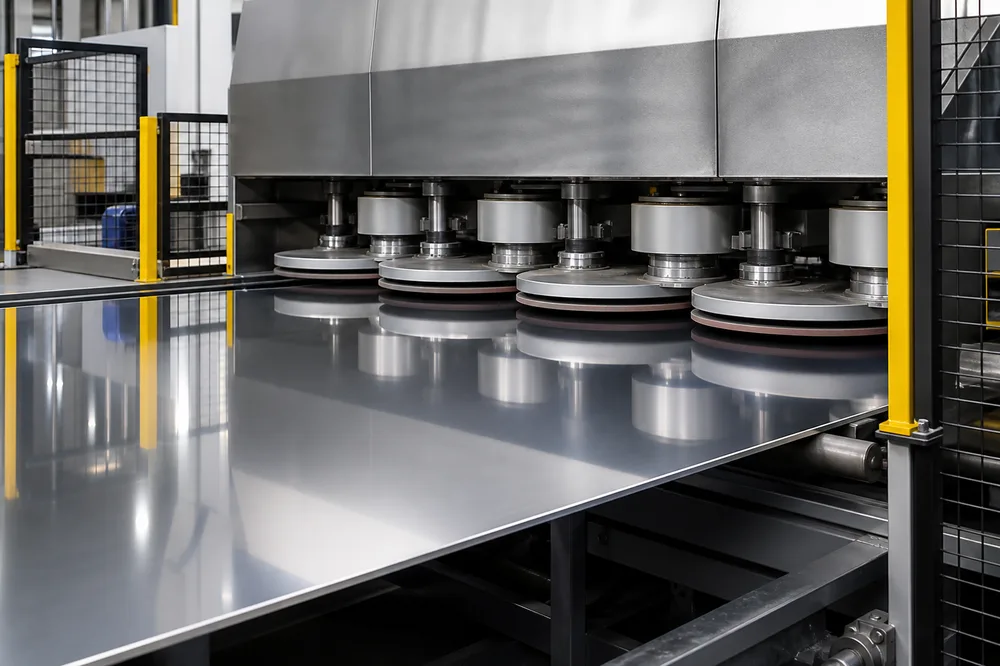
No.4 finish is produced by the eight-unit abrasive-belt polishing configuration (three back-side units, five top-side units), creating a uniform short-grain directional pattern. Hairline finish is produced downstream by the dedicated four-head hairline machine, creating continuous long linear grain. Both finishes run on the same coil-to-coil line in one pass; the process sequence (No.4 only, hairline only, or No.4 + hairline) is selected per order. For process control details, see our hairline finish control guide and No.4 finish guide.
>Application Industries
- Steel coil surface-finishing plants
- Metal coil service centers
- Decorative metal coil processors
- Coil producers requiring No.4 or hairline surface treatment
- Integrated polishing and protective-film application lines
- Kitchen and sanitary-ware coil processors (sinks, worktops, appliance panels) requiring No.4 or hairline finishes
- Architectural and decorative panel producers (elevator cladding, facade panels) in India, the Middle East and Southeast Asia
For titanium coil applications, see our titanium coil polishing line.
Specific steel grades, downstream products, and finish acceptance standards are To Be Confirmed for each application.
Optional Configurations
- Paint color selected from buyer-approved paint swatches
- Installation and commissioning supervision according to the contract
- Project-specific line layout and control configuration: Custom Available
- Abrasive selection, finish recipe, and acceptance criteria: To Be Confirmed
- Final coil ID arrangement and working-width configuration: To Be Confirmed
After-sales Service
The documented supply scope includes operation and maintenance manuals plus operation and maintenance training. Installation supervision, commissioning responsibilities, site preparation, and acceptance procedures must be defined in the final contract and technical agreement.
Call to Action
Contact GLORY MACHINERY with your material grade, coil thickness, coil width, coil weight, coil ID/OD, required surface finish, target line speed, and finish-acceptance criteria. Our engineering team will review the application and prepare a project-specific technical configuration.
Product Gallery
Technical Specifications
Material
| Parameter | Documented Value |
|---|---|
| Material form | Steel coil |
| Material grade | To Be Confirmed |
| Incoming surface condition | To Be Confirmed |
The technical document identifies the raw material as steel but does not provide an approved grade list.
Thickness
| Parameter | Documented Value |
|---|---|
| Coil thickness | 0.3-3.0 mm |
| Recoiler auxiliary vertical-belt limit | Maximum 1.2 mm; clamping jaws are recommended above 1.2 mm |
Width
| Source Location | Documented Value |
|---|---|
| Production-line overview | 650-1,550 mm |
| Raw-material parameters | 650-1,600 mm |
| Decoiler and entry equipment | Maximum 1,600 mm |
| No.4 polishing units | 650-1,550 mm maximum |
| Hairline machine | 150-1,550 mm maximum |
| Recoiler | Maximum 1,550 mm |
Approved working width: To Be Confirmed. The source contains different limits for the complete line and individual machines.
Coil / Sheet Size
| Parameter | Documented Value |
|---|---|
| Product form | Coil-to-coil continuous strip |
| Maximum incoming coil OD | 1,800 mm |
| Maximum finished coil OD | 1,800 mm |
| Material preparation table coil-diameter range | 1,200-1,600 mm |
| Sheet size | Not applicable to the documented continuous coil process |
Coil Weight
| Parameter | Value |
|---|---|
| Maximum entry coil weight | 25 MT |
| Maximum exit coil weight | 25 MT |
| Material preparation table | 25 MT |
| Loading trolley | 25 MT |
| Decoiler | 25 MT |
| Unloading trolley | 25 MT |
Maximum entry/exit coil weight confirmed at 25 MT.
Coil ID / OD
| Parameter | Documented Value |
|---|---|
| Raw-material coil ID | Source text is formatted as Φ5.08 mm; correct value To Be Confirmed |
| Decoiler expansion range | 474-525 mm |
| Recoiler expansion range | 475-508 mm |
| Maximum coil OD | 1,800 mm |
The final incoming and finished coil ID requirements must be confirmed against the approved mandrel configuration.
Line Speed
| Equipment / Section | Documented Value |
|---|---|
| Maximum line speed | 60 m/min * |
| Decoiler linear speed | Maximum 60 m/min |
| Recoiler winding speed | Maximum 60 m/min |
| Loading trolley movement speed | Maximum 6 m/min |
| Unloading trolley movement speed | Maximum 6 m/min |
* Maximum line speed. Continuous operation at 60 m/min depends on material, thickness, width, abrasive sequence and finish requirements. Guaranteed production speed by material, thickness, width, abrasive sequence, and required finish is To Be Confirmed.
Surface Finish
| Finish | Configuration |
|---|---|
| No.4 | Eight polishing units: three back-side units and five top-side units |
| Hairline | One four-head hairline finishing machine |
| Finish acceptance criteria | To Be Confirmed |
Power
| Parameter | Documented Value |
|---|---|
| Approximate total installed capacity | 800 kW |
| No.4 polishing-head motor | 55 kW per documented polishing unit |
| Recoiler main motor | 110 kW |
| Decoiler main motor | 45 kW variable-frequency motor |
| Rear pinch-roll motor | 45 kW |
| Hydraulic-station pump motor | 11 kW |
Final connected load, operating consumption, breaker capacity, and cable schedule are To Be Confirmed after configuration approval.
Voltage
| Source Location | Documented Value |
|---|---|
| General unit data | 3-phase 380 VAC +/-5%, 50 Hz +/-1% |
| Control-system section | 3-phase 415 VAC +/-5%, 50 Hz +/-1% |
| Process-control description | 430 VAC / 50 Hz, maximum fluctuation 5% |
| Control power | 230 VAC and 24 VDC |
Approved main power supply: To Be Confirmed. The source contains three different main-voltage values.
Machine Configuration
| No. | Main Equipment | Quantity |
|---|---|---|
| 1 | Material preparation table | 1 set |
| 2 | Loading trolley with telescopic guard plate | 1 set |
| 3 | Front support arm | 1 set |
| 4 | Paper recoiler | 1 set |
| 5 | Hydraulic decoiler | 1 set |
| 6 | Pinch roll, five-roll leveler, side guide, and crop shear | 1 set |
| 7 | 1650 No.4 polishing machine | 8 sets |
| 8 | Four-head hairline machine | 1 set |
| 9 | Cleaning and drying system | 1 set |
| 10 | Double-sided film applicator | 1 set |
| 11 | Rear four-roller pinch roll and guide roller | 1 set |
| 12 | Rear support arm | 1 set |
| 13 | Paper feeder | 1 set |
| 14 | Unloading trolley | 1 set |
| 15 | Recoiler with EPC and auxiliary recoiling device | 1 set |
| 16 | Filtration system | 1 set |
| 17 | Hydraulic system | 1 set |
| 18 | Pneumatic system | 1 set |
| 19 | Electrical control system | 1 set |
Additional documented parameters:
| System | Documented Value |
|---|---|
| Hydraulic pressure | 14 MPa |
| Hydraulic flow | 30 L/min |
| Hydraulic-oil capacity | Approximately 450 L |
| Hydraulic medium | N68 anti-wear hydraulic oil, supplied by buyer |
| Pneumatic pressure | 0.4-0.7 MPa |
| Air supply | 0.8-1.0 m3/min, supplied by buyer |
| Filtration accuracy | Maximum 50 micrometers |
| Filtration volume | 100 m3/h |
| Filtration supply pressure | Minimum 0.25 MPa |
| Approximate line footprint | 37,000 mm long x 8,000 mm wide |
| Minimum documented workshop | 40 m long x 8 m wide x 6 m high |
Customization
| Item | Availability |
|---|---|
| Paint color | Buyer-selected paint swatch |
| Production-line layout | Custom Available, subject to approved foundation and service clearances |
| PLC/process control configuration | Custom Available according to the approved control requirements |
| Abrasive sequence and finish recipe | To Be Confirmed through sample processing and technical review |
| Coil ID, coil weight, and working width | To Be Confirmed before design release |
| Electrical standard and main voltage | To Be Confirmed for the installation country and site |
Professional Selling Points
1. Integrated Coil-to-Coil Process
The documented line combines coil loading, decoiling, strip preparation, polishing, hairline finishing, cleaning, film application, and recoiling in one production sequence.
2. Eight-Unit No.4 Polishing Configuration
The line includes eight No.4 polishing units: three for back-side processing and five for top-side processing.
3. Four-Head Hairline Finishing
A separate four-head hairline machine is included for linear abrasive surface treatment after the No.4 polishing stages.
4. Wide Documented Thickness Range
The technical document specifies coil processing from 0.3 to 3.0 mm. The approved material grade and width must be confirmed for each application.
5. Powered Coil Handling
Hydraulic loading and unloading trolleys, powered mandrels, pressure arms, and front/rear support arms are documented for incoming and finished coil handling.
6. EPC-Guided Recoiling
The recoiler uses an EPC correction system with optical detection, control, servo-valve actuation, and position feedback to control winding alignment.
7. Integrated Cleaning and Drying
Four cleaning brushes, stainless steel pumps, high-pressure blowers, and air knives are documented for cleaning and drying the processed strip.
8. Double-Sided Film Application
The film applicator uses two air shafts, film-applying rollers, and magnetic-powder brakes to apply protective film after surface processing.
9. Centralized Grinding-Fluid Filtration
The documented nonwoven-fabric filtration system provides centralized filtration and chip removal for water-soluble grinding fluid.
10. PLC and Touchscreen Control
The line is controlled through PLC-based coordinated control and an industrial touchscreen interface, with manual and automatic operating modes documented.
11. Hydraulic and Pneumatic Integration
Dedicated hydraulic and pneumatic systems support coil handling, mandrel expansion, support-arm movement, clamping, tensioning, and other machine functions.
12. Defined Site and Utility Interfaces
The source document identifies electrical, compressed-air, cooling-water, foundation, workshop, and crane responsibilities for project planning. Final site values must be confirmed in the approved technical agreement.
Related: rotary disc 8K mirror polishing machine for sheet and coil 8K mirror finishing.
>Suitable Materials
| Material | Status |
|---|---|
| Steel coil | Documented |
| Specific stainless steel grades | To Be Confirmed |
| Titanium, aluminum, copper, and other nonferrous alloys | To Be Confirmed through engineering review and sample testing |
The source document states steel coil but does not provide an approved grade list, yield-strength range, or incoming-surface specification.
Suitable Surface Finishes
| Finish | Documented Process |
|---|---|
| No.4 | Multi-head abrasive-belt polishing |
| Hairline | Four-head abrasive hairline finishing |
| Protective film | Double-sided film application after cleaning and drying |
| Other brushed or specialty finishes | To Be Confirmed through process testing |
Finish roughness, gloss, scratch pattern, color consistency, and acceptance standards are To Be Confirmed.
Suitable Industries
- Steel coil service centers
- Coil surface-finishing plants
- Decorative metal coil processors
- Steel mills with downstream surface-finishing operations
- Coil producers requiring integrated polishing, cleaning, film application, and recoiling
- Contract metal finishers processing No.4 and hairline coil surfaces
Application Notes
- The documented thickness range is 0.3-3.0 mm.
- The source contains width values of 650-1,550 mm and 650-1,600 mm; approved working width is To Be Confirmed.
- Maximum entry/exit coil weight: 25 MT.
- Material grade, yield strength, surface condition, required abrasive sequence, and finish-acceptance criteria must be reviewed before quotation release.
- Sample processing is recommended before guaranteeing a finish for a new material or application.
Frequently Asked Questions
1. What type of production line is this?
It is an oil-wet coil-to-coil polishing and grinding line that integrates coil loading, decoiling, strip feeding and leveling, No.4 polishing, hairline finishing, cleaning, drying, film application, tensioning, and recoiling.
2. Which materials can the line process?
The technical document identifies the raw material as steel coil. Specific stainless steel grades, other alloys, yield-strength limits, and incoming-surface requirements are To Be Confirmed.
3. What material thickness can be processed?
The documented coil thickness range is 0.3-3.0 mm. The auxiliary vertical-belt recoiling device is documented for material up to 1.2 mm; clamping jaws are recommended for thicker material.
4. What is the working width?
The source contains different limits: 650-1,550 mm in the production overview and up to 1,600 mm in the raw-material and entry-equipment sections. The No.4 polishing units and recoiler are documented to 1,550 mm. Approved working width is To Be Confirmed.
5. What surface finishes are included?
The documented configuration includes No.4 abrasive-belt polishing and four-head hairline finishing. Other finishes and their acceptance criteria are To Be Confirmed through process testing.
6. How many polishing heads are included?
The equipment list specifies eight No.4 polishing units: three for the back side and five for the top side. It also includes one hairline machine with four grinding heads.
7. What production speed is documented?
The maximum line speed is 60 m/min. The decoiler and recoiler are both rated up to 60 m/min. Guaranteed speed depends on material, width, thickness, abrasive sequence, and finish requirements.
8. What is the maximum coil weight?
The maximum entry and exit coil weights are 25 MT.
9. What coil ID and OD are supported?
Maximum coil OD is documented as 1,800 mm. The source’s raw-material coil-ID entry is incorrectly formatted, while the decoiler and recoiler expansion ranges are 474-525 mm and 475-508 mm respectively. Final incoming and finished coil IDs are To Be Confirmed.
10. Does the line include cleaning and drying?
Yes. The documented system uses four cleaning brushes, stainless steel pumps, eight high-pressure vortex blowers, and air knives. Water-system details and final operating conditions must be confirmed for the project.
11. Is protective-film application included?
Yes. A double-sided film applicator with two air shafts, film-applying rollers, and magnetic-powder brakes is included in the documented configuration.
12. How is recoiling alignment controlled?
The recoiler includes an EPC correction system using a detection lens, light source, control module, servo valve, and feedback sensor to maintain winding alignment.
13. What utilities must the customer provide?
The customer is documented as responsible for the incoming electrical supply, cooling-water connection, compressed-air source, air compressor, dryer, air tank, gear oil, hydraulic oil, lubricating oil, and commissioning materials. Final interface values must be confirmed in the technical agreement.
14. What workshop space is required?
The line footprint is stated as approximately 37,000 mm long by 8,000 mm wide. The minimum workshop requirement is documented as 40 m long by 8 m wide by 6 m high, with a crane rated for at least 25 t. Service clearances and final foundation layout are To Be Confirmed.
15. Are manuals, training, and installation support included?
Operation and maintenance manuals plus operation and maintenance training are included in the documented scope. Installation supervision and the final division of site responsibilities are subject to the contract and approved project scope.
Related reading: No.4 stainless steel finish · consistent hairline stainless steel finishes · 1300mm coil-to-coil polishing line – 1300mm coil-to-coil polishing machine line (case study)
WeChat
Scan the QR Code with WeChat